Set Digital Output Logic
This guide shows you how to configure the OV20i's digital outputs to control external devices based on inspection results. The camera has 2 digital outputs that operate with True/False logic to trigger sorting mechanisms, indicator lights, alarms, or other automation equipment.
When to Use Digital Outputs: Automated sorting systems, pass/fail indicator lights, reject mechanisms, alarm systems, PLC communication, or any external device that needs to be triggered based on inspection results.
Prerequisites
- OV20i camera system set up and connected
- Active recipe with inspection logic configured
- External device to control (optional for testing)
- Basic understanding of digital I/O concepts
Digital Output Specifications
The OV20i provides 2 digital outputs accessible via the M12 connector:
| Output | Pin # | Wire Color | Function |
|---|---|---|---|
| Digital Output 1 | 10 | Violet | Configurable output |
| Digital Output 2 | 11 | Gray/Pink | Configurable output |
Operating Logic:
- True = Output ON (24V)
- False = Output OFF (0V)
Step 1: Access Node-RED Editor
1.1 Navigate to IO Block
- Open your active recipe in Recipe Editor
- Click "IO Block" in breadcrumb menu
- Click "Configure IO" to enter Node-RED editor
1.2 Verify Node-RED Interface
Checkpoint: You should see the Node-RED flow editor with the node palette on the left side.
Step 2: Add Digital Output Node
2.1 Locate Output Node
- Find "Output" node in the left panel (Overview section)
- Drag "Output" node onto the flow canvas
- Double-click node to configure

2.2 Configure Output Settings
Node Configuration:
| Setting | Options | Description |
|---|---|---|
| Output Pin | DO0, DO1 | Select which physical output to control |
| Initial State | OFF, ON | Starting state when system boots |
| Name | Custom text | Optional label for identification |
2.3 Output Configuration Steps
- Select Output Pin:
- DO0 = Digital Output 1 (Pin 10, Violet wire)
- DO1 = Digital Output 2 (Pin 11, Gray/Pink wire)
- Set Initial State:
- OFF = Output starts in OFF state (recommended)
- ON = Output starts in ON state
- Name the Node:
- Use descriptive names like "Reject_Signal" or "Pass_Light"
- Click "Done" to save configuration
Step 3: Connect Logic to Output
3.1 Basic Pass/Fail Output
For simple pass/fail indication:
- Add "Final Pass/Fail Output" node (if not already present)
- Connect: Final Pass/Fail → Output Node
- Result: Output activates when inspection passes
3.2 Inverted Logic (Fail Signal)
To trigger output on inspection failure:
- Add "function" node between pass/fail and output
- Configure function node:
// Invert pass/fail signal - ensure boolean output
msg.payload = !msg.payload;
return msg;
- Connect: Final Pass/Fail → Function → Output Node
- Result: Output activates when inspection fails
3.3 Custom Logic from Classification Results
When using classification or other inspection data:
- Add "function" node to convert results to boolean
- Configure function for your logic:
// Convert classification result to boolean
// Example: Activate output for specific class
if (msg.payload.class === "Defective") {
    msg.payload = true;  // Turn output ON
} else {
    msg.payload = false; // Turn output OFF
}
return msg;
- Connect: Data Source → Function → Output Node
3.4 Boolean Conversion Examples
For different data sources, always convert to boolean:
From confidence values:
// Activate if confidence below threshold
msg.payload = (msg.payload.confidence < 0.8);
return msg;
From ROI results:
// Activate if any ROI failed
msg.payload = msg.payload.roi_results.some(roi => !roi.pass);
return msg;
The Output node requires boolean input (true/false). Always ensure your logic produces boolean values before connecting to the Output node.
Step 4: Create Pulse Output (Recommended)
4.1 Why Use Pulse Output
Pulse output is recommended because:
- Provides clear signal indication
- Prevents output from staying ON indefinitely
- Better for triggering external equipment
- Easier to troubleshoot signal timing
4.2 Add Trigger Node
- Add "trigger" node from Function section
- Place between logic source and output node
- Double-click trigger node to configure
4.3 Configure Trigger Settings
Pulse Configuration:
| Setting | Recommended Value | Description |
|---|---|---|
| Send | True | Initial signal to send |
| Then wait | 500ms | Pulse duration |
| Then send | False | Signal after delay |
| Extend delay | Disabled | Don't extend on new messages |
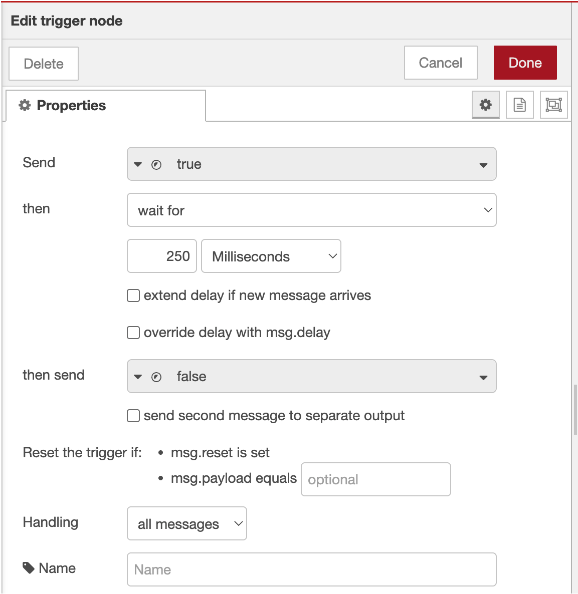
4.4 Trigger Configuration Steps
- First Output:
- Send:
boolean→true - This turns the output ON
- Send:
- Delay Settings:
- Then wait for:
500milliseconds - Then send:
boolean→false - This turns the output OFF after delay
- Then wait for:
- Advanced Options:
- Extend delay if new message arrives: Unchecked
- Stop existing delay if new message arrives: Checked
- Click "Done" to save


4.5 Wire Pulse Configuration
Connect nodes in this order: Logic Source → Trigger → Output Node
Example flow: Final Pass/Fail → Trigger → Output (DO0)
Step 5: Deploy and Test Configuration
5.1 Deploy Flow
- Click "Deploy" button (top-right corner)
- Verify deployment success message
- Check node status indicators
5.2 Monitor Digital I/O Status
Use the built-in I/O monitoring screen:
- Navigate to "Digital I/O" page in main interface
- Observe output status in real-time
- Check "Last state change" timestamps
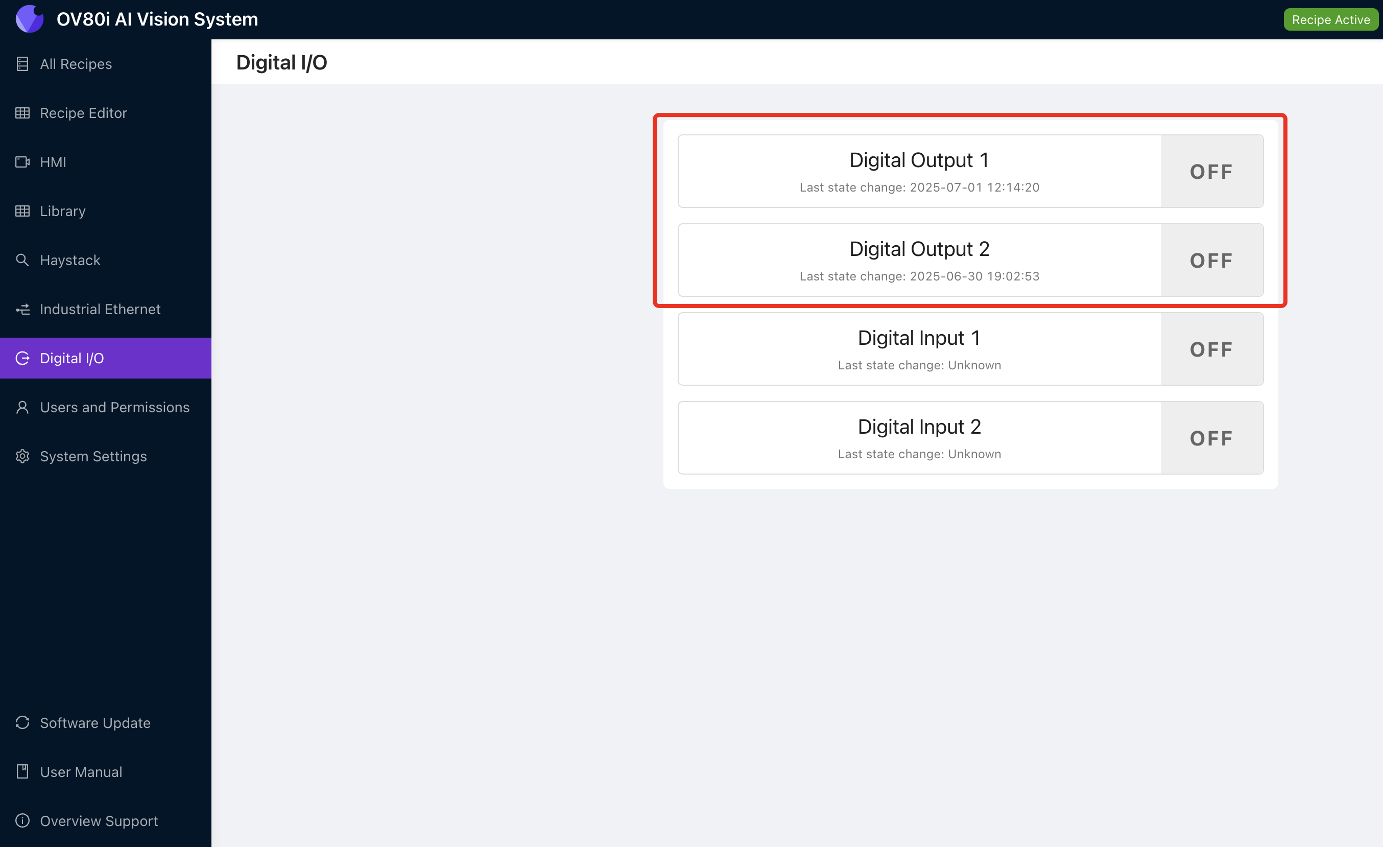
I/O Status Screen shows:
- Current output state (ON/OFF)
- Last state change timestamp
- Real-time status updates
5.3 Test Output Activation
Manual Testing:
- Add "inject" node for testing
- Configure inject node:
- Payload:
boolean→true - Name: "Test Output"
- Payload:
- Connect: Inject → Trigger → Output
- Click inject button to test output
- Verify output activation in I/O status screen
Step 6: Advanced Output Configurations
6.1 Multiple Output Control
Control both outputs simultaneously:
- Add separate output nodes for DO0 and DO1
- Connect same logic source to both outputs
- Use different trigger delays if needed
6.2 Conditional Output Selection
Route to different outputs based on conditions:
- Add "switch" node from Function section
- Configure routing rules:
// Route based on classification result
if (msg.payload.class === "Large") {
    return [msg, null]; // Send to first output (DO0)
} else if (msg.payload.class === "Small") {
    return [null, msg]; // Send to second output (DO1)
}
return [null, null]; // No output
- Connect switch outputs to respective output nodes
6.3 Delayed Output Sequences
Create timed output sequences:
- Add multiple trigger nodes with different delays
- Configure sequence timing:
- First trigger: 100ms pulse
- Second trigger: 500ms delay, then 200ms pulse
- Connect in series for sequential activation
Step 7: Integration Examples
7.1 Sorting System Integration
Two-way sorting setup:
- DO0 (Output 1): Good parts conveyor
- DO1 (Output 2): Reject bin actuator
Final Pass/Fail → Switch Node → Trigger → DO0 (Pass)
                             → Trigger → DO1 (Fail)
7.2 Alarm System Integration
Multi-level alarm system:
- DO0: Warning light (minor defects)
- DO1: Alarm horn (major defects)
Classification Logic → Function (Check severity) → Appropriate Output
7.3 PLC Communication
Simple PLC handshake:
- DO0: Inspection complete signal
- DO1: Part reject signal
All Block Outputs → Format for PLC → Trigger → DO0
                  → Reject Logic → Trigger → DO1
Step 8: Troubleshooting Output Issues
8.1 Output Not Activating
| Problem | Check | Solution |
|---|---|---|
| No output signal | Node connections | Verify all wires are connected |
| Logic never triggers | Input conditions | Check pass/fail logic configuration |
| Timing issues | Trigger settings | Adjust pulse duration |
| Wrong pin active | Output pin selection | Verify DO0/DO1 configuration |
8.2 Using I/O Status for Troubleshooting
The Digital I/O screen helps identify:
- Current Output State: See if output is actually changing
- Last State Change: Verify timing of output activation
- State History: Track output behavior over time
Troubleshooting with I/O Screen:
- Output shows "OFF" always: Logic may not be triggering
- Output shows "ON" always: Missing pulse configuration
- No timestamp updates: Check Node-RED connections
- Rapid state changes: Logic may be triggering too frequently
8.3 External Device Issues
| Problem | Cause | Solution |
|---|---|---|
| Device doesn't respond | Voltage mismatch | Verify 24V compatibility |
| Intermittent operation | Wiring issues | Check M12 connector wiring |
| Delayed response | External device timing | Adjust pulse duration |
Step 9: Testing and Validation
9.1 Systematic Testing
Test each output systematically:
| Test | Expected Result | Status |
|---|---|---|
| Manual trigger DO0 | Output 1 activates for pulse duration | ☐ |
| Manual trigger DO1 | Output 2 activates for pulse duration | ☐ |
| Pass condition | Correct output activates | ☐ |
| Fail condition | Correct output activates | ☐ |
| I/O status updates | Timestamps show state changes | ☐ |
9.2 Production Validation
Before deploying to production:
- Test with actual parts and inspection conditions
- Verify output timing meets external device requirements
- Confirm electrical connections are secure
- Document output assignments for maintenance
9.3 Performance Verification
Monitor these aspects:
- Response time: Output activation delay after inspection
- Reliability: Consistent output behavior over time
- Timing accuracy: Pulse duration matches configuration
Success! Your Digital Outputs are Ready
Your digital output system can now:
- Control external devices based on inspection results
- Provide pulse signals for reliable triggering
- Support multiple output configurations for complex automation
- Integrate with PLCs and sorting systems for production automation
- Monitor output status through the built-in I/O interface
Ongoing Maintenance
Regular System Checks
- Monitor I/O status screen for consistent operation
- Verify output timing remains within specifications
- Check electrical connections at M12 connector
- Test manual triggers periodically to ensure system health
Troubleshooting Resources
- Use I/O status screen for real-time diagnostics
- Check Node-RED debug panel for logic issues
- Verify external device specifications match output capabilities
- Document any configuration changes for future reference
Next Steps
After configuring digital outputs:
- Set up digital input triggers if needed for external control
- Configure PLC communication for integrated automation
- Implement safety interlocks for production environments
- Create automated monitoring for system health